插件功能

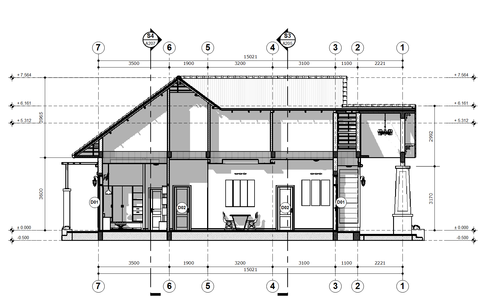
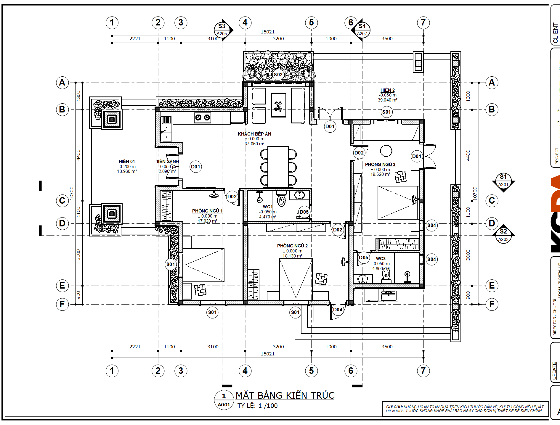
VBO轴网是用于在SketchUp模型中创建建筑柱轴网并将其放置在布局中的工具集。它还将剖面符号标记到布局中的SketchUpModel视图。
系统要求: Windows OS 10或更新版本(仅限PC) SketchUp 2024或更新版本 。

插件用法

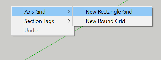
1、创建网格: 点击VBO网格的工具栏按钮,如果有任何网格系统是以前创建的,该工具将显示网格。如果不是的话,就没有表演了。可以将新网格添加到最近的系统或空白系统。 单击鼠标右键,然后选择”网格/新建矩形网格”或”网格/新建圆形网格”。然后,可以使用该工具为新网格系统的主方向绘制矢量。
2、编辑网格
2.1
将鼠标悬停在网格的实体上,这些函数基于工具选择的内容。
在网格基点(原点)上悬停 选定的网格系统将变为红色,鼠标光标将变为平移图标。将鼠标拖动到要将网格移动到的位置。这个动作只会将网格绕着氧平面移动。拖动时按住Shift键可以选择网格的级别(高度)。 上下文菜单: -删除网格 -获取布局代码 -跟踪轴 -清除轴
2.1.2
悬停在网格的基轴气泡上 选定的轴将变为蓝色,鼠标光标将变为旋转图标。拖动鼠标围绕网格的bae点旋转网格。
第一个触摸的气泡也会添加一个flip命令。如果要再次翻转,请选择另一个气泡。
上下文菜单: -更改名称函数 -复制 -获取布局代码 -跟踪轴 -清除轴
2.1.3
悬停在轴的气泡上 选定的轴将变为红色,鼠标光标将变为移动图标。拖动鼠标沿系统方向移动网格。 上下文菜单: -更改名称函数 -删除 -复制 -获取布局代码 -跟踪轴 -清除轴
2.1.4
在维度上悬停 选定的维度将变暗,鼠标光标将变为铅笔图标。双击文本以编辑尺寸。此测量将影响(移动)系统基点的下一个轴。
2.2功能
2.2.1、删除网格 删除选定网格。
2.2.2、清除轴 移除所有网格和轴。
2.2.3、获取布局代码 见3.2。
2.2.4、更改名称函数 该工具将要求您为网格输入一个”名称函数”。这将添加到当前网格系统的第一个轴。其他轴将根据字母表规则命名。
2.2.5、复制 向网格添加新轴。新轴将放置在选定轴(500 mm)旁边。命名将自动更新。
2.2.6、删除 删除选定轴 2.2.7,跟踪轴 见3.1。
3、导出网格
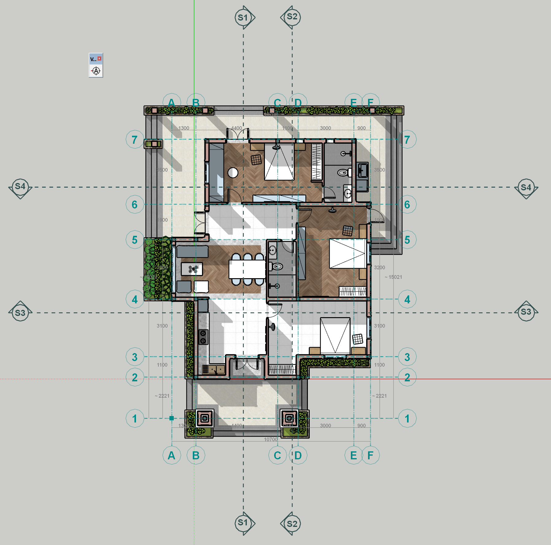
3.1、跟踪轴 退出工具时将不显示网格。因此,如果需要跟踪网格,选择此命令,程序将创建一组构造线来调整轴。
3.2、获取布局代码(仅适用于Windows PC) 这个特性创建了一个ruby代码,用于根据在skp模型中创建的网格信息在布局中重新绘制axis系统。填写表格,然后将代码放入剪贴板。将代码粘贴到LayOut中的Ruby控制台并按Enter键运行它。 设置窗体: -从边界偏移气泡 以当前模型的长度单位定义气泡到SketchUp模型边界的距离。如果将其保留为零,则将网格放置在SketchUp模型的边界内。 -布布尔半径 以当前模型的长度单位定义气泡的半径。 -尺寸 定义程序如何放置轴网尺寸。 -长度单位 为尺寸定义布局的长度单位 -抑制维度单位 定义尺寸标注的长度单位抑制。
4、剖面标记
4.1、显示剖面
4.2、获取布局代码。

重要提示

– 您必须通过在 LayOut 程序中找到菜单“扩展/Ruby 控制台”来检查您的 LayOut 是否可以使用此插件。如果找不到,请尝试以下步骤:

如果您打算在 Mac 上使用它,请不要购买此插件。

关闭所有 LayOut 窗口,然后转到 SketchUp,选择菜单“文件/发送到 LayOut”以重新打开它。

如果您使用的是 2020 或更新版本,并且无法通过“发送到 LayOut”命令在 LayOut 中找到控制台,请安装并保留 2019 版本,不必激活或使用它,只是为了更新版本可以拥有 LayOut 的 Ruby 控制台。

通过在不检查您的系统的情况下购买此插件,可能会拒绝某些技术支持。

版本:2.1.0

在购买本产品之前,请确保您已阅读并同意这些条件。因为这笔费用是不可退还的。

您可以在三台可以同时运行的独立计算机上激活您的许可证。

VBO Grids is a toolset for creates Architectural Columns Grids in SketchUp Model and place them on LayOut. It also tags the Section symbols to the SketchUpModel View in LayOut, creates and manages the level tags to the SketchUpModel View in LayOut.

.

Features:

Grids Tool

Level Picker Tool

User Manual

.

Requirements:

  • Windows OS 10 or newer (PC ONLY)
  • SketchUp 2020 – 2023

Important:

– You have to check your LayOut if it can use this plugin by finding the menu ‘Extensions/Ruby Console’ in LayOut Program. If you can not find it, please try those steps:

  • Don’t buy this plugin if you plan to use it on a Mac.
  • Close all LayOut windows, then go to SketchUp, choose menu ‘File/Send To LayOut’ to re-open it.
  • If you are using 2020 or newer and can not find the console in LayOut by ‘Send To LayOut’ command, please install and keep 2019 version, not have to activate or use it, just for the newer versions can have the LayOut’s Ruby Console.

By buying this plugin without checking your system, some technical support could be refused.

Version: 2.1.0.1

1. Create Grids:

  • Hit the VBO Grid’s Toolbar button, if there were any grid system was created before, the tool will show the grids. If not, there’s nothing show. You can add a new grid to a recent system or a blank system.
  • Right-click and choose Grids/New Rectangle Grid or Grids/New Round Grid. Then you can youse the tool to draw a vector for the main direction of the new grid system.

2. Edit Grids

  • 2.1. Hover your mouse on the Grids’ entities, the functions are based on what is selected by the tool. See below
  • 2.1.1. Hover on a Grid’s Base Point (Origin)
  • The selected Grid system will turn Red, the mouse cursor will change to the Pan icon. Drag your mouse to where you want to move the grid to. This action only moves the Grid around the OXY plane. Hold Shift Key while dragging will let you choose the level(height) of the Grid.
  • Context menu:
  • – Remove Grid
  • – Get Code for LayOut
  • – Trace Axises
  • – Clear Axises
  • 2.1.2. Hover on a Grid’s Base Axis’ Bubble
  • The selected axis will turn Blue, the mouse cursor will change to the Rotate icon. Drag your mouse to rotate the grid around its bae point. The first touched bubble will add a flip command, too. If you want to flip again, select the other bubble.
  • Context menu:
  • – Change Name Function
  • – Duplicate
  • – Get Code for LayOut
  • – Trace Axises
  • – Clear Axises
  • 2.1.3. Hover on an Axis’ Bubble
  • The selected axis will turn Red, the mouse cursor will change to the Move icon. Drag your mouse to move the grid along the direction of the system.
  • Context menu:
  • – Change Name Function
  • – Remove
  • – Duplicate
  • – Get Code for LayOut
  • – Trace Axises
  • – Clear Axises
  • 2.1.4. Hover on a Dimension
  • The selected dimension will turn DarkRed, the mouse cursor will change to the Pencil icon. Double-Click to the text to edit the dimension. This measurement will affect(move) the next axis from the system’s base point.
  • 2.2. Functions
  • 2.2.1. Remove Grid
  • Remove the selected Grid.
  • 2.2.2. Clear Axises
  • Remove all the grids and axes.
  • 2.2.3. Get Code For LayOut
  • See 3.2.
  • 2.2.4. Change Name Function
  • The tool will ask you to input a “name function” for the grid. This will add to the first axis of the current grid system. Other axises will be named by the alphabet rule. For examples:
Name Function
First Axis
Next Axises
A
A
B, C, D…
A1
A1
A2, A3, A4,…
AB
AB
AC, AD, AE…
aa
aa
ab, ac, ad…
  • 2.2.5. Duplicate
  • Add a new axis to the grid. The new axis will be placed next to the selected axis (500 mm). Naming will be updated automatically.
  • 2.2.6. Remove
  • Remove the selected axis
  • 2.2.7. Trace Axises
  • See 3.1.

3. Export Grids

  • 3.1. Trace Axises
  • The Grids will not be shown when you exit the tool. So if you need to trace the grid, choose this command and the program will create a group of construction lines to modulation the axes.
  • From Version 2.1.0:  The plugin will give an optional  settings to user

插件界面

授权购买

点击这儿

VBO_Grids_V2.1.0.1轴网工具
声明:本站所有插件资源,如无特殊说明或标注,均为本站原创发布。任何个人或组织,在未征得本站同意时,禁止复制、盗用、采集、发布本站内容到任何网站、书籍等各类媒体平台。如若本站内容侵犯了原著者的合法权益,可联系我们进行处理。